


By Dirk Loeffler
This article was originally published in the September/October 2026 issue of The New Brewer.
In craft brewing, operational efficiency often starts with treating every part of the brewery as a documented, repeatable process—not a habit. Nowhere is that concept more fitting than in the cleaning-in-place (CIP) room.
The Sinner’s Circle, the 67-year-old framework behind every cleaning cycle a brewery runs, is exactly that kind of process: four measurable inputs, traded against each other under real limits, in service of a consistent result. Understood and engineered correctly, it is not a sanitation footnote, but one of the most direct efficiency levers a brewery has.
When the conversation comes to operational efficiency in a brewery, safety, cleaning, and sanitizing rarely come up as topics. Yet often there are tens of thousands of dollars hidden in potential savings when it comes to variables such as chemicals, water, CO₂, and downtime. Cleaning and sanitizing are rarely considered from an efficiency standpoint; instead, they are viewed as a necessary process that nobody really likes doing.
I vividly remember working with the engineering department of a major brewery. We had proposed a few cleaning and sanitizing changes that, once implemented, would amount to significant savings. However, the engineer felt bothered by this project and said, “I need to work on real projects that are more important.”
Cleaning is often treated as overhead: a program (if you are lucky) someone came up with many years ago, running on fixed times, adjusted only when something goes wrong, and often not even then. We just clean it again and blame the chemicals, shifting the responsibility from the brewery to the supplier.
Undoubtedly, there are big differences between caustic and acid cleaners, but they generally involve the concentrations required to clean. If a piece of equipment suddenly does not come clean using the same chemical out of the same drum or tote, something other than the chemical is likely the cause. Sometimes it is the chemical, but more often the underlying issue is more complex.
That is a missed opportunity, because cleaning does not have to be a black box. When approached correctly, the process runs on a documented, quantifiable framework of its own—ironically, based on parameters that predate most modern Lean methodologies by decades.
TACT: A Framework
In 1959, German chemist Herbert Sinner published the model the sanitation world still uses today. In North America, it is usually referred to as the Sinner’s Circle. In Europe, it is called the Synergistic Circle, my preferred title not only because I am German, but because it better describes the synergy within the circle.
On the plant floor, we often refer to it simply as TACT, an acronym for Time, Action (mechanical energy), Chemistry, and Temperature. All three names describe the same principle: a desired cleaning result is produced by some combination of chemicals, mechanical energy, temperature, and contact time, and those four inputs can be traded, within limits, against one another. (See Figure 1.)
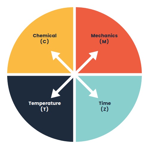
The result of any cleaning process is the sum of four interchangeable inputs. The equation is simple:
CR = C + M + T + Z
CR is the cleaning result (treated as a constant, since we ideally always want to achieve the same repeatable result: CLEAN!).
C is the chemical energy contributed by the chemical(s): composition, concentration, activity, etc. (Note: water is included here.)
M is the mechanical energy applied to the soil (flow velocity, flow turbulence, impingement, pressure, etc.).
T is the temperature of the cleaning solution.
Z (from German, Zeit = time) is the contact time.
We also refer to these four parameters as the Operational Parameters.
The emphasis here is on “interchangeable within limits.” The Circle is not a free-trade zone where any parameter can be substituted infinitely for one or more of the other parameters. Each of the four parameters has a lower and upper limit, set by either chemistry or physics, and by equipment, cost, or safety. It is important that we know and understand what those limits actually are.
Designing and engineering the cleaning process deliberately around these four operational parameters, rather than guessing, is what separates a brewery that runs a genuinely efficient cleaning program from one that is quietly compensating for one or several incorrectly set or utilized parameters. When that happens, the brewery pays for it in water, chemicals, energy, or downtime, and this expense is never accounted for as a cleaning cost; or worse, the equipment never really gets clean. (The perception of “clean” now enters the conversation, but that’s a subject for another article.)
Two other groups of parameters sit above the Synergistic Circle or Operational Parameters, determining how much room a brewery actually has to maneuver:
Equipment Parameters: These include the materials being used (e.g., 304 or 316L stainless steel, finishing, etc.), equipment design (are all surfaces contacted by the cleaning solution? Are there drains?), often determined and fixed in place at the design and installation phase of the brewery.
System Parameters: These include the chemical composition and quantity of the soil in and on equipment, frequency of cleaning, soil load of cleaning solution, quality of process water (particularly hardness and chlorides), and the environment in which the brewery is situated (e.g., hot, dry, wet, humid, etc.).
Get these parameters wrong and no amount of clever adjustment of the Circle’s four operational inputs will be able to fully compensate, which is exactly why truly efficient sanitation starts during the conversation when a tank farm or brewhouse is specified.
Mechanical Energy: The Overlooked Efficiency Variable
Of the four operational parameters in the circle, mechanical energy is often the least understood and most neglected, even though it’s critical to the success of the cleaning. While chemicals can, to some degree, compensate for poor mechanical energy (the circle again), it is often mechanics, and to a much lesser degree chemistry, at fault when a CIP program should work on paper, but does not.
It is important to understand that chemicals do not remove soil. Instead, they prepare the soil for removal through saponification, hydrolyzation, emulsification, and other chemical reactions. Here is where mechanical action comes into play. Once the soil is prepared and the bond to the surface has been dissolved, sufficient flow velocity in a pipe or a sufficiently thick, falling film of solution on a tank wall is required to produce turbulent flow, which creates the mechanical energy needed to remove the soil and keep it from redepositing.
Laminar flow, no matter how fast it feels, does not produce sufficient mechanical energy to do that job. Liquid, as it increases in speed and velocity, starts to react with the wall surfaces of the equipment and the friction and roughness of the wall surfaces begin producing vortices alongside the surface. These vortices create the mechanical energy required to physically remove the soil. Think of it as a brush in liquid form.
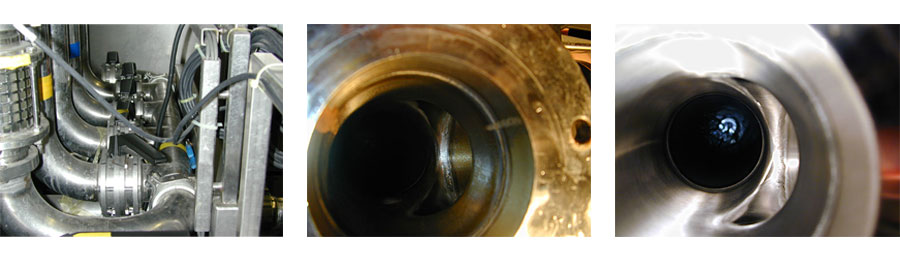
The photos below show this principle in action in the field. A brewery cracked the valve on the CIP return to compensate for the imbalance between supply and return. The left photo shows the piping coming from the tank with the cracked valve, with visible soil remaining after the cycle (center photo). Without changing any other parameters, we simply opened the cracked valve and ran a CIP cycle. The photo on the right shows the same pipe after a single CIP cycle with the valve open 65% of the time. Laminar flow caused by a low flow velocity was replaced with turbulent flow in a high velocity flow, creating the mechanical energy that was lacking before. (The determination as to whether laminar or turbulent flow is present in piping and hoses can be accomplished by calculating the Reynolds number—see bottom of page.)
Not all mechanical problems are this easy to resolve and high-quality chemicals are still required to achieve optimal results, using all four of our operational parameters. This is why operational efficiency and cleaning engineering need to be in the same conversation. A poorly designed pipe run with lots of turns and elbows, an undersized or oversized pipe run, a supply and/or return pump without variable frequency drive (VFD), or a cracked valve quietly restricting flow to balance a CIP system does not just risk a failed clean—it forces the operator to compensate with more chemical, more time, or more heat than the job actually requires. That compensation shows up directly on the utility and/or chemical invoice, CIP cycle after CIP cycle.
Getting fluid mechanics right can be tricky. Reducing a DN80 (3-inch) pipe run to DN65 (2½-inch) while maintaining the same flow rate substantially increases velocity and friction loss—potentially approaching three times the original loss, depending on the pipe’s actual internal diameter and operating conditions. (See Table 1 below.) Increasing the run to DN100 (4-inch) lowers velocity and friction loss below the turbulent threshold entirely and may allow entrained or released air to accumulate at high points.
Table 1: Flow Volume at Common CIP Pipe Diameters
| Pipe diameter (DN) | 40 | 50 | 65 | 80 | 100 | 125 |
| Inches | 1½” | 2″ | 2½” | 3″ | 4″ | 5″ |
| Flow volume (m³/h) | 9 | 14 | 24 | 36 | 54 | 86 |
Pipe sizes and diameter transitions should therefore be selected using hydraulic calculations and appropriate reducer and venting arrangements. Avoid changes in diameter whenever possible. Pipe sizing and pump selection deserve the same deliberate engineering as the chemistry. A brewery running a balanced, properly sized CIP circuit with variable-frequency drives on its supply and return pumps is not just cleaning more reliably; it is running the most efficient possible version of that CIP, because it is not paying for a mechanical shortfall with one or more of the other circle parameters.
Time: The Parameter Tied Directly to Revenue
Time is the parameter with the most direct line to operational efficiency. Downtime is money. Equipment turnaround is throughput, and throughput is revenue, which is exactly why production is always trying to minimize the cleaning window. But time also has a real lower limit: saponification, dispersion, and the wetting of dried soil are time-dependent chemical reactions. Good quality chemical products can reduce the time, but no amount of clever chemistry can make these reactions instantaneous.
The efficiency approach here is not a shorter fixed time. It is replacing fixed times with verifiable instrument endpoints wherever the chemistry and physical setup allow it. A prerinse programmed to run until the return water runs clear, rather than for a flat five minutes, saves water and cycle time in a system that cleared early. It also saves your CIP solution from contamination in a heavily soiled system that a fixed timer would have cut short.
A CIP program built entirely on fixed times, without conductivity or pH endpoints anywhere in the sequence, is a program guessing at its own most valuable parameter rather than measuring it. And guessing is the opposite of operational efficiency. A tank rinsing for five minutes despite needing just 90 seconds to run clear wastes thousands of gallons each year. Multiply this by a number of tanks and this is real money.
Temperature & Chemistry: Where Efficiency Meets Risk
Temperature is the parameter most likely to turn an efficiency conversation into an operational safety discussion. A caustic CIP cycle generally needs to reach at least 50°C (120°F) to saponify protein and fatty soils effectively. However, while brewery tanks are built and engineered to handle high internal pressures (often up to 15–30 psi), they can implode under a negative vacuum pressure of just –1.5 psi to –3 psi (–0.1 to –0.2 bar). There is hardly a more expensive form of cleaning inefficiency than an imploded tank and the production loss that goes along with it.
The fix is the same one that the rest of this framework calls for: establishing in writing, with the tank and relief-device manufacturers, a validated maximum rate of temperature change per tank, and programming step-up and step-down rinses to stay inside it, rather than relying on a generic rule of thumb.
Chemistry carries its own quiet efficiency cost. Chemical concentration has a real lower limit. Dilute a detergent below the point where its surfactants and alkalinity can function, and no amount of added time or heat can compensate for it. Chemicals also have a real upper limit, past which the excess concentration attacks gaskets and stainless steel without any added cleaning benefits. Using the right quality chemicals and monitoring the concentrations, either with titration or via temperature-compensated conductivity rather than assumption, is the difference between a program using and dosing exactly what the soil load requires, and a program that is overdosing chemicals as insurance or compensation for a mechanical or time shortfall that is never diagnosed.
Other Hidden Efficiency Traps: The Incompatibility Issue
Sodium hydroxide (NaOH) is generally the preferred workhorse alkali in brewery cleaning. It provides the bulk of the free alkalinity responsible for saponifying and removing organic soil and is the chemical most brewery CIP programs are built around.
However, NaOH is a strong base that will react readily with any acid gas it contacts, including carbon dioxide. Put liquid caustic in contact with CO₂ gas, and the following reaction proceeds essentially to completion:
2 NaOH (aq) + CO₂ (g) → Na₂CO₃ (aq) + H₂O (l)
Sodium hydroxide mixed with carbon dioxide gas yields sodium carbonate plus water. On the surface this looks like an unremarkable acid-base neutralization, and chemically that is exactly what it is. However, for cleaning, it means you started with a strong alkali carrying a large amount of usable free alkalinity, and then converted a potentially significant portion of your free alkalinity into sodium carbonate. Sodium carbonate is a considerably weaker alkali with a fraction of the cleaning power of the NaOH it replaced.
Every bit of NaOH consumed this way is free alkalinity that is no longer available to saponify the protein and fatty soil it was dosed to remove. And this reaction is happening continuously and invisibly, wherever your caustic solution is exposed to a CO₂ atmosphere, which, in a working brewery cellar, is almost everywhere. Open drums or other containers slowly neutralize into sodium carbonate.
A particular application is often overlooked here. In a keg washer, residual carbon dioxide is in almost every keg. During purging, some of this gas remains and reacts with the caustic CIP cleaning cycle. After a certain number of kegs, an NaOH-based solution becomes mainly sodium carbonate, and is no longer able to clean your kegs properly.
Some titration kits only titrate for total alkalinity, not free alkalinity. Make sure you use a test kit that has a reagent that precipitates sodium carbonate and bicarbonate first before titrating for free NaOH, and titrate frequently. Failing to do so may not only be compromising operational efficiency, but may also be jeopardizing product quality and brand reputation.
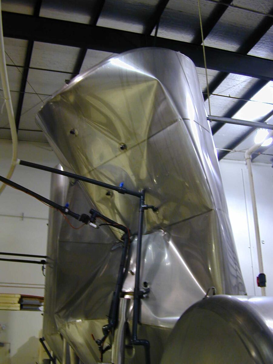
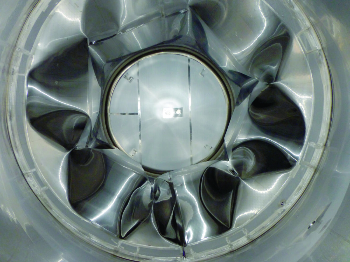
In a tank, the reaction of sodium hydroxide with carbon dioxide is a net negative volume reaction, meaning the total gas volume in the tank rapidly decreases, causing a vacuum to form. Every mole of CO₂ absorbed disappears from the gas phase and becomes dissolved carbonate or bicarbonate. Without getting into the math of caustic absorption capacity, it is important to understand that even a relatively small CIP charge can remove several cubic meters of headspace gas, with potentially catastrophic consequences.
The photos below show tank implosions that occurred after running a caustic CIP solution into tanks filled with carbon dioxide without prior purging.
Operational Efficiency Through Optimized CIP
As you can see, there are potentially significant savings hidden in your cleaning and sanitizing processes. This article barely scratches the surface of these savings, but it quickly becomes clear that optimizing brewery cleaning procedures can carry significant benefits, both from a quality standpoint and an operational efficiency standpoint.
The Sinner’s, or Synergistic, Circle gives you the framework. Calculating the Reynolds number—the standard design threshold for pipe circuits to ensure turbulent flow and mechanical soil removal (see sidebar)—and flow velocity gives you the mechanical half of the equation that chemistry alone cannot cover. And understanding what temperature and an ordinary acid-base reaction can do to a tank will keep you out of the kind of trouble that ends up as a cautionary tale in someone else’s conference presentation.
None of this requires an engineering degree to apply. It simply requires the discipline to calculate rather than assume. Measure your actual flow velocity instead of trusting the original drawing; measure your rinse endpoint instead of trusting a set time; measure the temperature swing your largest tank will actually see instead of trusting that “it has always been fine.” Every tank collapse and chronic cleaning failure I have ever been called in to look at had a moment, well before the failure, where either knowledge or a simple measurement would have prevented it.
Dirk Loeffler has been working in the craft brewing industry since 1992, specializing in cleaning, sanitizing, chemical safety, metallurgy, and enzymes.
The Reynolds Number
The determination as to whether laminar or turbulent flow is present in piping and hoses can be accomplished by calculating the Reynolds number, a dimensionless ratio of inertial forces to viscous forces in a fluid:
Re = (v × D) / ν = (v × D × ρ) / μ
Where v is the mean fluid velocity, D is the internal pipe or hose diameter, ν is the kinematic viscosity of the fluid (μ / ρ), μ is the absolute dynamic viscosity, and ρ is the fluid density.
A low Reynolds number means viscous forces dominate and the flow stays smooth and laminar; a high Reynolds number means inertial forces dominate and the flow becomes chaotic and turbulent.
For flow in a circular pipe, the transition from laminar to turbulent flow begins at a Reynolds number of around 2,000. However, in practice engineers do not design systems to be anywhere near that number because the zone from roughly 2,000 to 4,000 is a transitional region where flow is neither reliably laminar nor turbulent. Fluid behavior in this range is difficult to predict. The practical design rule is to target a Reynolds number at or above 4,300, which provides sufficient margin and ensures you are always in solid turbulent territory, with flow not collapsing back toward laminar under normal process variations.
In an existing brewery pipe system, the pipe or hose diameter is generally fixed and the viscosity of your cleaning solution is essentially constant, which means the Reynolds number, and whether you get turbulent flow or not, is almost entirely controlled by one variable: flow velocity. The practical conclusion is that an aqueous CIP solution needs a flow velocity of at least 2 m/sec (roughly 6.5 ft/sec) to reliably achieve turbulent flow in a typical CIP pipe run.
Because the required velocity is fixed (2 m/sec), the flow volume you must circulate to hit that number depends entirely on pipe diameter. Table 1 gives the flow volume needed to reach 2 m/sec for common pipe sizes; the relationship is not linear, because flow volume scales with the cross-sectional area of the pipe (proportional to the diameter squared), so a comparatively modest increase in pipe size demands a much larger increase in pump capacity to maintain the same velocity.
This has direct, sometimes expensive consequences for pipe sizing and pump selection. Consider two real-world examples:
Example 1: Reducing Pipe Diameter. A run of DN80 pipe requires 36 m³/h to hold 2 m/sec, with an associated pressure loss of roughly 0.55 bar (~8 psi) per 100 m of pipe. Reduce that same run to DN65 while holding the flow volume at 36 m³/h, and the velocity rises to about 3 m/sec—comfortably turbulent—but the pressure loss more than triples, to roughly 1.8 bar (~26 psi) per 100 m. You have bought better mechanical energy at the wall at the cost of a pump that now has to work considerably harder against friction.
Example 2: Increasing Pipe Diameter. Go the other direction—increase DN80 to DN100 while holding the same flow volume—and velocity drops from 2 m/sec to about 1.25 m/sec. That is now well below the threshold for reliable turbulent flow. And worse, an oversized pipe run creates hollow space that can allow air to be drawn into the system from vertical runs (the Venturi effect), introducing air entrainment problems on top of the lost mechanical energy.
The practical design rule that follows from both examples is to avoid changing pipe diameter within a CIP circuit wherever you possibly can; and if you cannot avoid it, never increase or decrease by more than about ½ inch in a single transition.


 Resource Hub